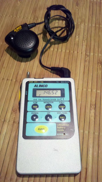
The Alinco DJ-C1 was made in the 1990s and was a groundbreaking ham radio micro-transceiver about the thickness of an iPhone 4 and with a smaller footprint nearly identical to that of a credit card. It was designed to work on the 2m FM Voice band at 300mW. It featured an integrated microphone, but had no internal speaker from the factory; One had to rely on an earphone or an external speaker/microphone unit such as the one shown above.
Over time, these micro radios evolved. The DJ-C4 came out at the same time as the C1, and was made for 440 MHz (70cm FM Voice). The DJ-C5 was a bit thicker and was the first to have an integrated speaker and work on both of the above bands. The latest one, the DJ-C7, lacks resemblance to these tiny relics of the late 90s aside from being smallish.
You can still find these micro-handheld transcievers at hamfests, swap meets and online auctions. I got mine from a friend that's happened upon two C1s and a C4 in the past year. I was immediately somewhat frustrated by the lack of a built-in speaker. I opened it up and found plenty of room in the back for a piezoelectric element, similar to what you find as the alarm speaker in digital wrist watches.
I couldn't find anything to salvage a piezo speaker out of, so I coughed up a couple of bucks at Radio Shack for one. I used a tiny screwdriver to pry the back cover off and to pry the element out of the case.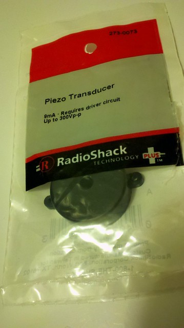
Disassembly of the DJ-C1 initially looks pretty straight-forward. There are three small philips screws on the back which give you access to the battery and the back of the circuit board. You'll have to open the back up and you'll want to disconnect the battery before proceeding. Unfortunately, most of the stuff we need access to is on the other side of the circuit board. You can't get the board out from the back, so leave the screws through the circuitboard attached. To remove the front plate, carefully peel the sticker and membrane buttons off, then remove the three screws found underneath.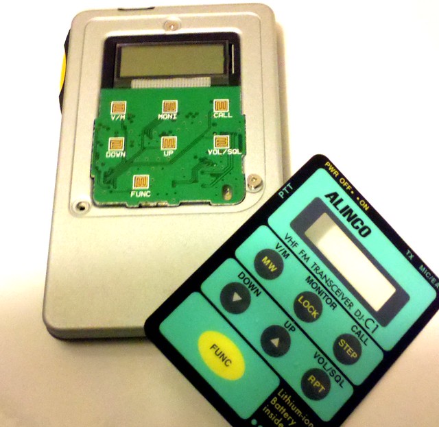
There aren't many places to pass wires from the back of the radio where the speaker will be to the front of the radio where they can attach to the solder pads for the audio jack, so I ran them between the legs of the transmit LED. With the front and back removed, you can slide the circuit board out of the rectangular plastic frame enough to get access to the solder pads with almost any kind of soldering iron. You can see the red and black wires here: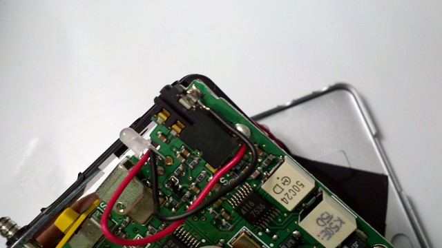
I taped the piezo element to the back case toward the bottom. The copper shield in the middle of the circuit board seen below will sit flush against the back case, so keep the speaker and wires clear of it. The piezo speaker is actually louder when it's taped to the back case than it is when it's hooked up to the audio jack by itself.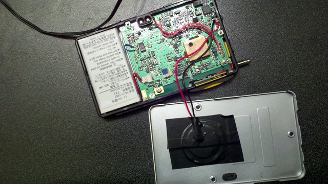
Gently re-assemble everything, making sure everything fits neatly inside. Re-position the speaker and wires as needed. I ended up placing a bit of tape inside to keep the speaker wires from getting in the way. Re-connect the battery, screw the front plate back on, re-attach the membrane buttons to the front, and test it before you button the thing back up.
The resulting speaker works, but isn't terribly loud. It's loud enough to get your attention from the office desk, and if you hold it up next to your ear, you can make out what's being said. This is all I expected from this hack. You'll want to hold on to that earphone or external speaker, though.
Here's some crappy cell phone video of it in action.
2012-02-07
Alinco DJ-C1 Hack: Internal Speaker
Posted by
Ax0n
Labels: Electronics, ham, hardware
blog comments powered by Disqus
Subscribe to:
Post Comments (Atom)


