- Tools to open your computer case
- A voltmeter or multi-tester, preferably a digital multimeter (DMM)
- A paper clip or a small piece of wire to use as a jumper.
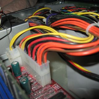 A friend of mine was having trouble with one of his computers. At first, it sounded like a power supply problem, so I gave him some advice on testing the power supply.
A power supply can make or break your computer. It's often one of the first components to fail because of the high temperatures and abundance of electrolytic capacitors. Heat and capacitors aren't usually a good combo, and running the computer with a clogged fan can raise temperatures in the PS high enough to damage the caps. A power supply may also take the brunt of the damage in a power surge, as well -- especially if the computer is turned off.
There are a few things to understand about the ATX Power Supply. First off, ATX power supplies are soft-triggered, meaning that they're always pulling a little bit of electricity from the wall. They're powered on not with a hard physical switch, but with an electronic relay activated by the motherboard. Therefore, a little bit of electricity has to be going to the motherboard even when the computer is off, so that it can tell when you have hit the power switch.
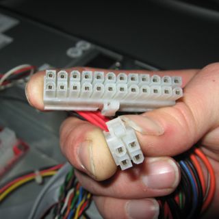
Another thing is that most newer computers require extra power for the motherboard, this comes in the form of two additional 12VDC wires and two additional grounds molded into a four-prong plug (called a P4 plug) that supplements the traditional ATX plug:
Before we begin testing, unplug the computer from the wall outlet, open the case, and unplug all the Power Supply cords from the motherboard, drives and all accessories. Notice that there are many black wires on the main ATX plug. If you have a DMM with an ohm-meter or continuity tester, you should check to make sure all of the black wires have continuity. These are all chassis ground wires, and you can use any one of them to test the for the power supply. Hook one test lead up to any black wire, then make sure that there is little to no resistance between that black wire and all the other black ones. Be sure to check the grounds on the P4 plug and Molex (hard drive) plugs.
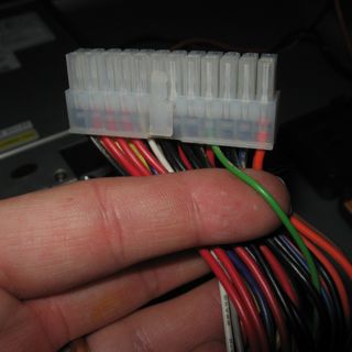
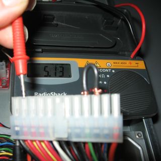
Now, you may plug the power supply into the wall outlet again. The only wire we need to test right now is the purple wire. Take note of it, as it may look a lot like the black wires or a blue wire if you don't have plenty of light. It will be the fourth wire in, next to the two adjacent yellow wires on the main plug as shown below:
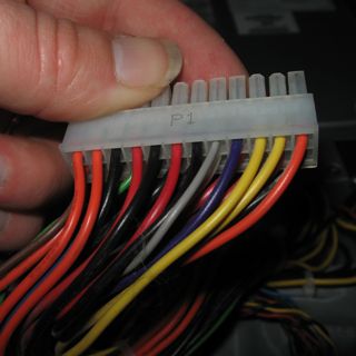
Test the voltage between this purple wire and ground. This is the "standby" power, and should be near 5VDC.
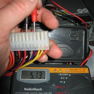
If this doesn't register any voltage, there may be a fuse blown internally to the power supply, or it could be something more catastrophic. If the voltage is wildly out of spec (like 2.3VDC or 8VDC), something is very wrong. Trash it and replace your power supply.
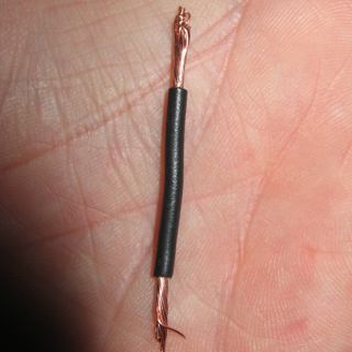
Now, you'll need your paper clip or a jumper wire. I chose a jumper wire because it's insulated and I didn't want to run the risk of hitting the jumper with my DMM's test probes. I'm just careful.
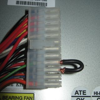
Find the green wire. This is the power-on wire.
When the green wire is jumpered to ground, the power supply fan should spin up. If this doesn't happen, something is wrong, but it could just be a clogged fan so you should at least check the voltages before you go shopping for a new power supply. Make SURE you jumper the green wire to a black wire, not the purple one. I don't know if it would hurt anything, but the PowerON wire is not designed to be hooked to anything other than ground.
I attached the ground probe to one of the ground wires by jamming it into the back of the ATX plug, so that I only have to fiddle with the positive test probe from here on out. That makes taking these pictures a little easier. ;)
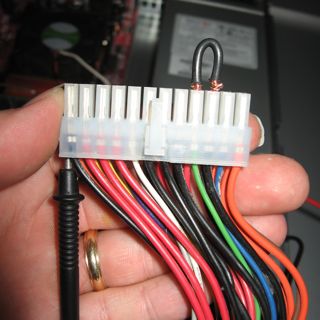
First, I tested the voltage of all of the red leads. These should be +5VDC. Not surprisingly, they are the same voltage as I saw on the Standby Power rail which should also be +5VDC. To be sure the power supply is intact, check ALL of the red, yellow, blue and orange wires on ALL plugs, even for the P4 and Molex hard drive power plugs. A single broken or damaged connection can be the difference between a healthy computer and one that's unstable or may not even boot.
Test all of the leads except for the brown, green, and gray ones. The green is obviously in use and working at this point. Brown and gray are both voltage sense connections that you don't need to bother with. Your power supply may or may not have a white wire. It's optional in the ATX specification but most new power supplies have them present. Use the table below to determine the voltage specifications for each color. Note that these are voltages as related to chassis ground (black wires). Again, if any of these voltages are wildly out of spec or you notice an open circuit (0 volts), you should probably replace the Power Supply or have it looked at by a competent computer repair professional. Opening up a Power Supply voids its warranty and exposes components that could probably hurt you even if it's unplugged.
| Color | Voltage |
| Purple (standby) | +5VDC |
| Red | +5VDC |
| Yellow | +12VDC |
| Orange | +3.3VDC |
| Blue | -12VDC |
| White (optional) | -5VDC |
Great write-up! I would like to point out something though that may lead the neophyte to improperly deciding a power supply is bad in some circumstances.
ReplyDeleteSwitching power supplies are designed to operate at a minimum load rating. This means if you power up the supply without anything plugged in, it's operating out of spec. While it won't hurt the supply, it will definitely give inaccurate readings. In some cases, the power supply won't fire up at all. This is even allowed in the ATX spec: "...The power supply may latch into a shut-down state." What I've seen in this instance is the fan will bump a little bit until you try to restart it. The ATX spec says that if minimum loads of 0.3A for 3.3V and 1.0A for +5.0V exist, all ratings must be met.
Usually what I do when I have a known bad power supply is to use one or two 10 ohm wirewound resisters. This is one of the few things Radio Shack still carries. A 10 ohm resistor between red (+5V) and black (Ground) will draw 0.5A at 2.5W. (5V / 10ohm = 0.5A; 5V^2 / 10ohm = 2.5W.) Two of these in parallel will draw a full amp - enough to drive the PS to spec, but usually only one will be enough to allow the PS to kick on.
Also, the +5VSB is usually derived from a separate linear regulator, and not the same switching regulator that supplies the main +5V rail. A linear regulator will maintain spec even when no current is being drawn. While it's a nice feature, we don't use a linear regulator for the main supply because it is less efficient (hotter) than a switcher, and certain characteristics of switching power supply technology allow them to be made with much smaller (and cheaper! and more reliable!) components.
That's cool, I haven't run into a power supply that won't fire up without a load and I probably would have written it off as a bad PS if I did. I have, however, seen voltages stray quite a bit (not what I call "wildly out of spec") from the proper voltage. Thanks for the update on getting more accurate diagnostics.
ReplyDeleteThanks ax0n, I just stumbled on this - nice! The pictures make the difference.
ReplyDeleteAnd thanks Paul - coming from the same background, I could not agree more. And now I must add my two cents.
Generally, is not a good idea to run any PSU without a proper load. If you have reason to suspect a problem, you cannot assume it will behave as expected. Even quality stuff can go bad but sadly, many PSUs are made in child slave labor factories and go through zero quality control. Anything that plugs in the wall can kill - do not trust that your deadly voltage circuits were wired, or are working, correctly.
Also, as Paul pointed out, you do not get reliable readings (though no reading is cause for concern when testing) without a load.
It is not that it won't fire up with out the load - though you still must fool the motherboard into thinking it is connected to the motherboard, it is that your readings will be inaccurate. You may get a good solid 5V with no load, but then it drops to 2.7V under load - not good.
Even the plug-in testers as seen at Newegg, which contain a dummy load, do not present a true load to the PSU (though they are great in a pinch, and I keep one in my bag).
The problem is, when using a multimeter as ax0n shows (with or without a proper load), or with a plug-in PSU tester, you still may have a bad PSU as there may be too much ripple (alternating current) riding the DC rails.
The only real way to properly test a PSU of any type is with an oscilloscope, and with the PSU under a realistic load.
Inserting a probe (multimeter or scope) into the heart of the computer is dangerous, a tiny slip may slice through several critical circuits printed on the board - and IMO, should be left to a trained technician.
So what should you do? Swap in a known good PSU.
JMHO
-bill
Good article; a picture is worth... I'm an experienced electronics technician and what the others have said about the dangers of hi-voltage (120 vac) is VERY true.
ReplyDeleteUsing a paperclip to jumper the green to black pins is fine if it is wrapped in electrical tape & nowhere near any circuitry or metal parts. This is not because of any normally present DC voltage present on either of these pins (all black pins are grounded - ZERO volts DC) but rather, if the PSU circuit is defective, a significant stray AC voltage may be present. On electronic equipment, the NESC & IEEE Std 80 industry standards consider 1.0 VAC to be the maximum allowable.
To test for dangerous (and damaging) stray AC voltage, simply use a digital volt/ohm meter (VOM); few PC techs have an oscilloscope available.
To start, the AC cord should be UNplugged from the wall outlet BEFORE attaching it to the PSU; don't plug the cord into the outlet just yet. Before attaching any jumper, as stated earlier, attach an OLD (as in: you don't care if you let all the smoke out of it) hard drive for proper PSU circuit loading.
Insert your jumper between the green pin and any black pin in the PSU-to-motherboard connector. Secure the black VOM lead to the bare metal of the PSU case, then, without touching the PSU case, plug the AC cord into the outlet. Proceeding in this order will prevent you from getting a jolt if the PSU circuit is damaged and a significant AC voltage is on the PSU case.
Handling only the insulated wires and connector, touch the red VOM probe to any black pin. A reading in excess of 0.5 VAC between the PSU case and a black pin is an indication of a defective (and unsafe) PSU; DO NOT use it even if the DC voltages appear to be within specs.
dear sir
ReplyDeletei have 24 pin power supply on green cable have 5 volt. but this compputer supply do not on computer . i checked out put capacitors, diod's & resistors ,
wht should i do plz tell me how to repair this supply this is my e mail id plz reply me on this
buttji82@gmail.com